10.3 冗余案例

案例要求
VLAN2、3、4 对网络稳定性的要求比普通教室要高得多。为了满足这一高可用需求,本次案例需要达成以下四个目标:
- 网关冗余设计:增加冗余网关(使用VRRP协议),确保单点网关设备发生故障时,网络仍能正常运行,实现用户无感知切换。
- 链路防环与负载均衡:使用MSTP协议解决因引入冗余链路而产生的网络环路问题,并实现不同VLAN间的流量负载分担。
实现步骤
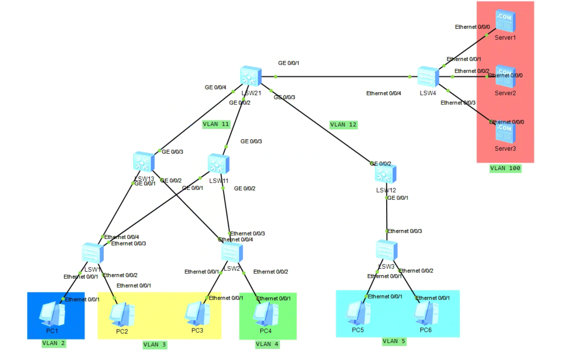
一、修改拓扑图
第一步,增加一个三层交换机LSW13,作为LSW11的冗余备份,如下图所示:
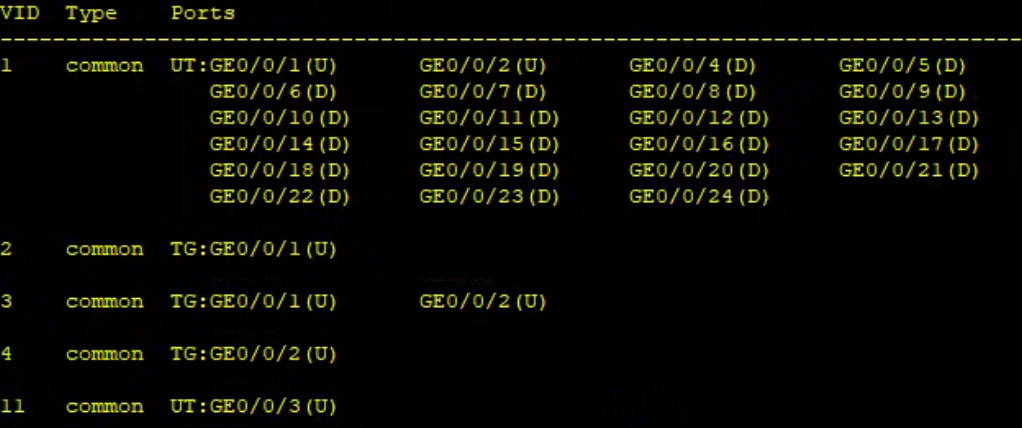
二、配置新设备 LSW13
在新添加的 LSW13 交换机中创建 VLAN 2、3、4、11,并将相应接口划分到这些 VLAN 中。配置完成后的结果如下图所示:
vlan bat 2 3 4 11
int g0/0/1
port link trunk
port trunk allow vlan 2 3
quit
int g0/0/2
port link trunk
port trunk allow vlan 3 4
quit
int g0/0/3
port link-type access
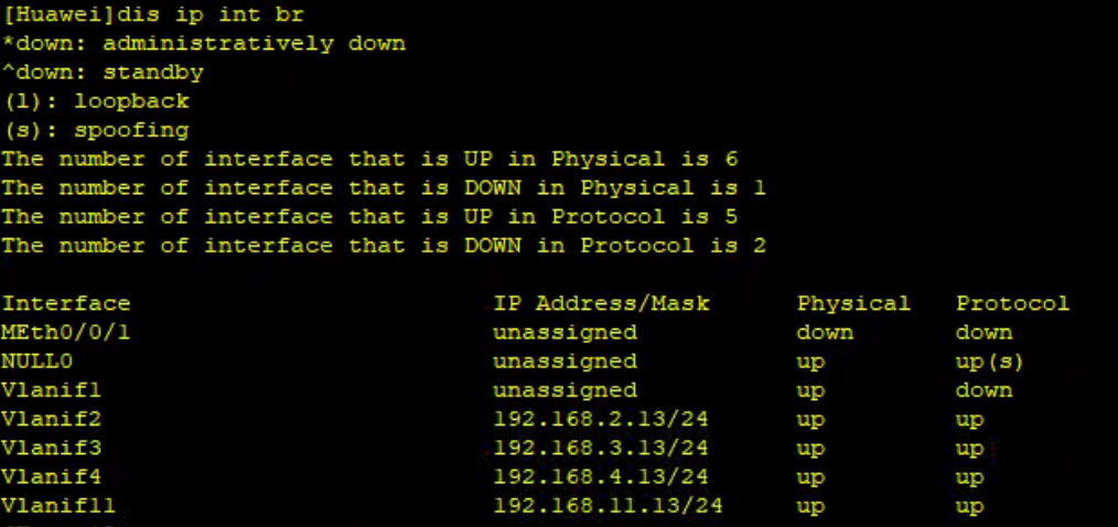
port default vlan 11同时为该交换机配置VLANIF接口及其IP地址:
| 接口 | IP地址/子网掩码 |
|---|---|
| VLANIF 2 | 192.168.2.13/24 |
| VLANIF 3 | 192.168.3.13/24 |
| VLANIF 4 | 192.168.4.13/24 |
| VLANIF 11 | 192.168.11.13/24 |
int vlanif 2
ip add 192.168.2.13 24
quit

int vlanif 3
ip add 192.168.3.13 24
quit

int vlanif 4
ip add 192.168.4.13 24
quit

int vlanif 11
ip add 192.168.11.13 24
quit
最后,还需要在新交换机上配置 RIP 协议,发布其直连网段,以便核心交换机能够通过冗余路径学习到相关路由:
rip 1
network 192.168.2.0
network 192.168.3.0
network 192.168.4.0
network 192.168.11.0
quit
配置结果如下:
三、补充相连交换机的对端接口配置
当我们把新设备 LSW13 接入现有网络时,除了配置 LSW13 本身,与之相连的其他交换机的对端接口也必须进行相应的 VLAN 配置,否则会导致二三层通信断路。
1. 核心交换机 LSW21
新增加的 LSW13 通过其 GE 0/0/3 接口与核心交换机 LSW21 的 GE 0/0/4 接口相连。为了保证两台设备能够通过 VLAN 11 互通并建立 RIP 邻居关系,必须在 LSW21 上将 GE 0/0/4 接口也划分到 VLAN 11 中:
# LSW21
int g0/0/4
port link access
port default vlan 11
quit
2. 接入交换机 LSW1 和 LSW2
LSW13 向下分别连接了底层的 LSW1 和 LSW2。为了让 VRRP 的心跳报文和业务流量能够正常透传,必须将 LSW1 和 LSW2 对应连接 LSW13 的新上行接口(此处设为 Ethernet0/0/4)配置为 Trunk 模式并放行对应 VLAN:
# LSW1
int e0/0/4
port link-type trunk
port trunk allow-pass vlan 2 3
quit

# LSW2
int e0/0/4
port link-type trunk
port trunk allow-pass vlan 3 4
quit
四、修改LSW11配置
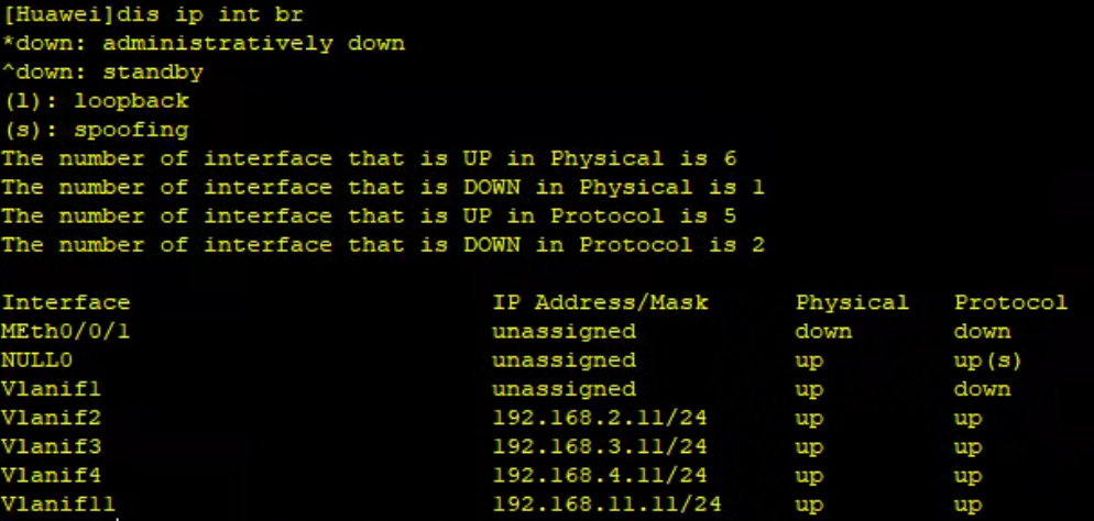
将LSW11上的VLANIF 2、3、4的IP地址从原来的192.168.x.1改成192.168.x.11。这是因为192.168.x.1将作为VRRP虚拟路由组的共享IP,需要将其保留出来。
int vlanif 2
ip address 192.168.2.11 24
quit

int vlanif 3
ip address 192.168.3.11 24
quit

int vlanif 4
ip address 192.168.4.11 24
quit
配置完成后的结果如下图所示:
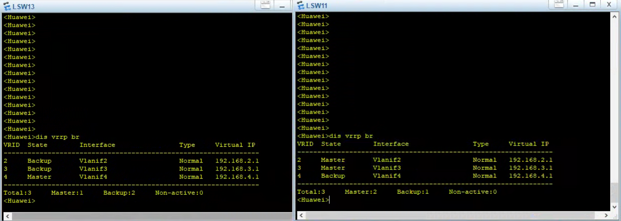
五、配置VRRP虚拟网关
接下来,将LSW11与LSW13上对应的VLANIF 2、3、4接口划分到同一VRRP虚拟路由组中,并设置不同的优先级以确定主备关系。
VRRP优先级配置要求:
| 交换机 | VRID | 优先级 | 角色 |
|---|---|---|---|
| LSW11 | 2 | 120 | 主设备 |
| 3 | 120 | 主设备 | |
| 4 | 100 | 备用设备 | |
| LSW13 | 2 | 100 | 备用设备 |
| 3 | 100 | 备用设备 | |
| 4 | 120 | 主设备 |
配置 VRRP:
# LSW11
int vlanif 2
vrrp vrid 2 virtual-ip 192.168.2.1
vrrp vrid 2 priority 120
quit

int vlanif 3
vrrp vrid 3 virtual-ip 192.168.3.1
vrrp vrid 3 priority 120
quit

int vlanif 4
vrrp vrid 4 virtual-ip 192.168.4.1
quit


# LSW13
int vlanif 2
vrrp vrid 2 virtual-ip 192.168.2.1
quit

int vlanif 3
vrrp vrid 3 virtual-ip 192.168.3.1
quit

int vlanif 4
vrrp vrid 4 virtual-ip 192.168.4.1
vrrp vrid 4 priority 120
quit
六、配置MSTP解决环路问题
环路分析
在我们的网络拓扑中,添加冗余网关 LSW13 并与 LSW1、LSW2 相连后,在包含多个 VLAN(如 VLAN 3)的二层网络中,形成了以下潜在环路:
LSW11 - LSW1 - LSW13 - LSW2 - LSW11 环路
如果不加控制,这种二层环路将导致广播风暴,使网络瘫痪。
MSTP整体规划
MSTP配置范围:需要在 LSW21、LSW11、LSW13、LSW1、LSW2 这五台交换机上配置MSTP
区域规划:
- 区域名称:CAMPUS
- 配置交换机:核心交换机 LSW21,汇聚交换机 LSW11、LSW13,接入交换机 LSW1、LSW2
实例0
- 映射VLAN:未映射到其他实例的所有VLAN
- 功能:负责区域间连接和基础连通性
- 主根桥:LSW21
- 备份根桥:LSW11
- 说明:核心交换机作为CIST根桥,确保整体拓扑稳定
实例1
- 映射VLAN:2 和 3
- 主根桥:LSW11
- 备份根桥:LSW13
- 说明:与VRRP配置一致,LSW11作为VLAN 2和3的VRRP主设备,因此将其配置为实例1的根桥,确保流量优先通过LSW11转发。
实例2
- 映射VLAN:4
- 主根桥:LSW13
- 备份根桥:LSW11
- 说明:与VRRP配置一致,LSW13作为VLAN 4的VRRP主设备,因此将其配置为实例2的根桥,确保流量优先通过LSW13转发。
第一步:配置LSW21(核心交换机)
# 启用MSTP
stp mode mstp
stp enable

# 配置MST区域参数
stp region-configuration
region-name CAMPUS

# 配置VLAN到实例的映射
instance 1 vlan 2 3
instance 2 vlan 4

# 激活区域配置
active region-configuration
quit

# 配置实例优先级
stp instance 0 root primary     # 作为实例0的主根桥
第二步:配置LSW11(汇聚交换机)
# 启用MSTP
stp mode mstp
stp enable

# 配置MST区域参数
stp region-configuration
region-name CAMPUS

# 配置VLAN到实例的映射
instance 1 vlan 2 3
instance 2 vlan 4

# 激活区域配置
active region-configuration
quit

# 配置实例优先级
stp instance 0 root secondary   # 作为实例0的备份根桥
stp instance 1 root primary     # 作为实例1的根桥
stp instance 2 root secondary # 作为实例2的备份根桥第三步:配置LSW13(汇聚交换机)
# 启用MSTP
stp mode mstp
stp enable

# 配置MST区域参数
stp region-configuration
region-name CAMPUS

# 配置VLAN到实例的映射
instance 1 vlan 2 3
instance 2 vlan 4

# 激活区域配置
active region-configuration
quit

# 配置实例优先级
stp instance 1 root secondary   # 作为实例1的备份根桥
stp instance 2 root primary # 作为实例2的根桥root primary 和 root secondary,交换机会自动将优先级设置为 0 和 4096,从而决定生成树的根节点。第四步:配置LSW1(接入交换机)
# 启用MSTP
stp mode mstp
stp enable

# 配置MST区域参数
stp region-configuration
region-name CAMPUS

# 配置VLAN到实例的映射
instance 1 vlan 2 3
instance 2 vlan 4

# 激活区域配置
active region-configuration
quit
第五步:配置LSW2(接入交换机)
# 启用MSTP
stp mode mstp
stp enable

# 配置MST区域参数
stp region-configuration
region-name CAMPUS

# 配置VLAN到实例的映射
instance 1 vlan 2 3
instance 2 vlan 4

# 激活区域配置
active region-configuration
quit完成以上配置后,网络中的环路问题将得到解决,同时保留了链路冗余的优势。MSTP将根据不同VLAN的实例配置,选择最优的转发路径,阻塞可能导致环路的端口。
结合VRRP和MSTP的配置,我们成功实现了一个具有高可用性的网络架构,能够应对设备故障和链路故障的情况,确保重要部门的网络服务不会中断。
最终结果: